{"title":"CsPbBr3 Perovskite Nanocrystals: Linking Orthorhombic Structure to Cubic Geometry through Atomic Models and HRTEM Analysis","authors":"Narayan Pradhan","doi":"10.1021/acsenergylett.5c00128","DOIUrl":null,"url":null,"abstract":"Cesium lead halide perovskite nanocrystals have reached one decade since their simpler synthesis method was reported by Kovalenko and co-workers in 2015. (1) Significant research progress has been made in designing and optimizing the reaction chemistry and optical properties of these emerging light-emitting nanocrystals. (2−9) However, despite the successes achieved for obtaining several such nanocrystals, CsPbBr<sub>3</sub> remained in the limelight because of its bright green emission and better phase stability. (3,4,7,10,11) Even in a reaction flask or centrifuge tube, the eye-catching brightness under UV light (12,13) truly excites researchers, and hence, these remained the representative nanocrystals to explore for investigating properties as well as applications of halide perovskite nanocrystals. (2,14−18) Some features of these nanostructures are indeed different, and hence, these occupy some unique positions among all colloidal quantum dots. One such case is their phase–shape relationship. These are largely reported in the orthorhombic phase but mostly in a cube shape. (1−3,19,20) There is also a report on size-dependent phase variation where smaller size is dominated with cubic phase, but these change to orthorhombic for larger sizes. (21) On the other hand, the blue emitting CsPbCl<sub>3</sub> nanocrystals are largely reported in the cubic phase with cubic shapes. (1,3) The case of CsPbBr<sub>3</sub> having orthorhombic phase and cube shape indeed puzzles as the orthorhombic phase has different atomic parameters but the cube shape has lengths that are equal along all three directions. These cubes are even so monodisperse that their superlattices (22−24) and long-range self-assembly are widely reported. (3,25) Hence, from the standard crystallographic point of view, this confuses from first glance, leading to the belief that these are in the orthorhombic phase. This prompted the writing of this Viewpoint as it was realized that detailed information might help newcomers in the field. In nanoscale synthesis, such exceptions are widely seen in shape modulations where the crystal growth follows paths different than as expected in bulk and facets are dominated by surface ligand binding ability. The CsPbBr<sub>3</sub> also remained in such a category of material whose crystal atomic parameters indeed remained unique from their crystal phase to their stability. Keeping this in mind, details of the phase–shape correlation of CsPbBr<sub>3</sub> nanocrystals are interpreted with their atomic models and reported in this Viewpoint. These are further supported with high-resolution transmission electron microscopy (HRTEM) image analysis. This Viewpoint is also written from the perspective of synthesis with basic characterization of these materials, which typically confuses new researchers in the field. Figure 1 presents the 3D atomic models of orthorhombic CsPbBr<sub>3</sub> (Figure 1a) and cubic CsPbCl<sub>3</sub> (Figure 1b) nanostructures in their respective cube shapes. Space groups and atomic parameters for each case are also inserted in each panel. For CsPbBr<sub>3</sub>, this remained different where three directions parallel to facets of cubes became two ⟨110⟩ and one [001]. These are assigned considering the space group <i>Pbnm</i> with atomic parameters <i>a</i> = 0.8207 nm, <i>b</i> = 0.8255 nm, <i>c</i> = 1.1759 nm. These can also be labeled considering the unit cell parameters <i>a</i> = 0.82 nm, <i>b</i> = 1.17 nm, <i>c</i> = 0.82 nm with space group <i>Pnma</i>, but in that case, the (<i>hkl</i>) values will be changed. For simplicity, here axes remained identical for both halides and the space-filled cubes are placed as per their exact orientations. Accordingly, for CsPbBr<sub>3</sub>, the projected atomic parameters became 1.164, 1.164, and 1.1759 nm, which remained almost identical. In this case, the [001] direction remained unaltered, but [100] and [010] directions were changed to two ⟨110⟩ directions as shown in Figure 1a. Hence, while viewed along the [001] direction, CsPbBr<sub>3</sub> showed 45° rotation to [100] and [010] directions. Accordingly, six facets of the orthorhombic CsPbBr<sub>3</sub> cube became (002), (002̅), (110), (1̅1̅0), (11̅0), and (1̅10), whereas for CsPbCl<sub>3</sub>, these remained as six {100}. In the space filled models, the number of atoms are taken arbitrarily just to represent the shape and are not in exact scale. Figure 1. Atomic models of (a) orthorhombic CsPbBr<sub>3</sub> and (b) cubic CsPbCl<sub>3</sub> viewed along [001] or <i>c</i> directions. Atomic parameters and space groups for each structure are inserted along with respective models. This suggests that six facets of the cube of CsPbBr<sub>3</sub> are not exactly identical even though it retains the shape symmetry of a hexahedron. Hence, the patterns of octahedral arrangements in the atomic models of this perovskite in different viewing directions along their facets are expected to be different. Figure 2a presents the octahedral perovskite atomic model viewed along the [001] direction, and the top and bottom facets here remained (002) and (002̅). These are labeled as {002} because standard planes parallel to these facets are {002} with d-spacing of 0.5879 nm. Accordingly, planes side-to-side are labeled as (110) having <i>d</i>-spacing of 0.582 nm and from corner-to-corner as (200) having <i>d</i>-spacing of 0.41 nm (Figure 2b). On the other hand, the octahedral atomic model viewed along [110] is presented in Figure 2c and the corresponding <i>d</i>-spacing of 0.5879 nm for (002) and 0.413 nm for (11̅2) are presented in Figure 2d, respectively. These labelings are as per the atomic models considered here, but for small crystals it becomes difficult to exactly predict the planes and viewing direction in their HRTEM images. Hence, how to exactly label facets as well as viewing directions becomes important as it could be random or specific considering the view along the [001] or [110] directions. This requires a detailed HRTEM analysis of these nanocrystals. However, before that the crystal phases of these nanocrystals are correlated to distinguish the orthorhombic and cubic phases from the data of powder XRD. Figure 2. Atomic models of CsPbBr<sub>3</sub> with (a) octahedra and (b) the standard two-dimensional structure having viewing direction [001]. The same octahedral model (c) and (d) two-dimensional ball model of CsPbBr<sub>3</sub> with viewing direction [110]. Cubes synthesized following the method reported by Kovalenko and co-workers (1) typically retain their size below 20 nm. To have larger size nanocrystals for obtaining intense and prominent XRD peaks, multifaceted polyhedral nanocrystals with more than 25 nm size are considered following the method reported using phenacyl bromide as the brominating agent. (26) The XRD of these nanocrystals is presented in Figure 3a where clear differences of (004) and (220) peaks are observed along with prominent small intense peaks confirming these are in the orthorhombic phase. The shape is here similar to the truncated form of a larger cube shape. Figure 3b presents the XRD of films of rhombic dodecahedron-shaped and cube-shaped CsPbBr<sub>3</sub> nanocrystals. (26) From the cube shape XRD, (004) and (220) peaks are clearly separated, confirming the orthorhombic phase. Peaks of the cubic phase have similar intense peaks, and for small size cubes, these two peaks are generally seen to be broad and merged. However, several reports with clear explanation already established the fact that these nanocrystals are in the orthorhombic phase. (3,26,27) For comparison, the variation of peak intensities is also observed in the rhombic dodecahedron-shaped nanocrystals which have different facets than the cube shape. In this case, (112) and (200) peak intensities are seen to be more intense than (002)/(110) peaks. XRD of these 12-faceted dodecahedron-shaped nanocrystals is presented here for comparison, and because of their small size, these peaks appear to be merged, resembling the peaks of the smaller size cubic-like phase of CsPbBr<sub>3</sub>. Variation of XRD peak intensities and sometimes peak splitting are related to several factors, and these might be due to the self-assembly obtained during drop casting, instrumental set up and use of the sample holder, sample preparation, size/shape of particles, and also their dispersity. However, these three examples are presented here as representative ones for comparison. Several such CsPbBr<sub>3</sub> nanocrystals are already reported with truncations of edges as well as vertices of cubes to show variation in peak intensities in their XRD. (26,28,29) To relate the facets and shape of these nanocrystals, possible formation of different faceted nanostructures which could originate from truncation of cube shapes or with independent nucleations are presented in Figure 3c. The <i>d</i>-spacing, corresponding (<i>hkl</i>) values, and combinations of planes resulting in a definite shape of nanocrystals are correlated. With exclusive planes having 0.58 nm (0.582 and 0.587 nm), only a cube can be formed as the total number remained 6. Similarly, with exclusive planes with <i>d</i>-spacing 0.41 nm (0.410 and 0.413 nm), 12 faceted nanocrystals would be formed as their total numbers remained 12, including two {200}, two {020}, and eight {112} facets. Furthermore, for the <i>d</i>-spacing of 0.67 nm (0.673 and 0.675 nm), either 4 faceted tetrahedron or 8 faceted octahedrons would be formed. Similarly, combinations of planes can result in 14, 18, and 26 faceted nanocrystals, as shown in the figure. All these shapes’ formations certainly depend on the adopted synthesis procedure; some are already reported, (26,29) and some are yet to be formulated. Figure 3. (a) XRD of ∼40 nm CsPbBr<sub>3</sub> polyhedral nanocrystals and inset showing its representative 3D atomic model. (b) XRD of cube and rhombic dodecahedron shaped CsPbBr<sub>3</sub> nanocrystals. Arrows marked as (112)/(020) peaks reflect its intensity is more in rhombic dodecahedron shape than cube shape nanocrystals. (c) Different (<i>h</i>, <i>k</i>, <i>l</i>) values and their combinations to reflect different faceted CsPbBr<sub>3</sub> nanocrystals. As stated above, the atomic parameters <i>a</i>, <i>b</i>, and <i>c</i> are different for orthorhombic phase, and hence, for a cube, three pairs of facets along three directions cannot be identical. However, as their <i>d</i>-spacings are very close to each other, these show similarity. Hence, confusion arises in labeling planes in HRTEM images whether to label a plane as (110) or (002) as their <i>d</i>-spacing difference cannot be distinguished from the fast Fourier transformed (FFT) patterns. Figure 4 presents one HRTEM image and both possible orientations for plane labeling. Figure 4a shows an HRTEM image of a truncated cube (∼20 nm), and the corresponding selected FFT patten is depicted in both Figure 4b and Figure 4d. Points with similar <i>d</i>-spacings in both FFTs are circled, where yellow is marked for the <i>d</i>-spacing of 0.58 nm and white for 0.41 nm. However, the third digit after the decimal in these cases cannot be identified to designate precisely these planes, and hence, the labeling can bring in different possible orientations. The model in Figure 4c presents a cube viewed along [11̅0], and that in Figure 4e is viewed along [001]; these are labeled as per the FFT labeling in Figure 4b and Figure 4d, respectively. Accordingly, planes having <i>d</i>-spacing of 0.58 nm and 0.41 nm are marked in both cases. Unless the crystal is larger and FFT collected from wider area, it is indeed difficult to identify planes and viewing directions for {110} and {002} or {200} and {112} planes. In most of the reports on cubes, HRTEM images are labeled with planes from side-to-side facets as {110} and corner-to-corner of the cube as {200} assuming the view or zonal axis as [001]. However, this can also be labeled with other possible views. Hence, in practical observation of the HRTEM in small size cubes, either way can be labeled because the HRTEM cannot provide distinguishable differences among {110} and {002} planes. Figure 4. (a) HRTEM of a truncated shape of a CsPbBr<sub>3</sub> cube nanocrystal. (b) Corresponding image selected area FFT pattern and (c) representation of model of the cube assuming the viewing direction as [11̅0]. (d) The same FFT as in panel b and the (e) representative model of a cube with viewing direction [001]. (f) Typical shape of cube with viewing direction [001] and a representative FFT pattern, (g) the model of cube along viewing direction [100] and its representative FFT pattern, and (h) representative atomic model of the cube along the viewing direction [201] and corresponding possible FFT pattern. (i) Atomic models showing the nanoplatelet along [001] and [110] directions. Space group for the models of orthorhombic CsPbBr<sub>3</sub> is Pbnm (62). The above analysis was for a cube nanocrystal aligned on the TEM grid with one of its facets toward the electron beam. However, the analysis might be different if the nanocrystal is rotated or precipitated with different orientation. Figure 4f presents a 3D atomic model of a cube of CsPbBr<sub>3</sub> viewed along [001] direction and the possible FFT pattern on this alignment. In this case, closest planes from center (000) with 90 deg intersects will have <i>d</i>-spacing 0.58 nm. Hence, these can be either of {110} and {002} facets, and in this case, these planes are labeled as (110) and (11̅0) as the viewing direction was assumed as [001]. Similarly, the same cube is shown along the viewing direction [100] where one of the edges of the cube remained along the zone axis and this is presented in Figure 4g. The expected FFT is also presented adjacent to the model, and in this case, two planes perpendicular to each other will have <i>d</i>-spacing of 0.58 and 0.41 nm, respectively. These can be labeled as per the viewing axis, and in this case, these became (200) and (020). The third possibility is the viewing along the vertices, and a representative one is presented in Figure 4h having viewing direction [201]. The corresponding FFT here will show planes having <i>d</i>-spacing of 0.41 nm with intersecting angle of 60°. Planes are assigned here assuming the viewing direction [201]. These three atomic models and their planes are labeled in orthorhombic phase of CsPbBr<sub>3</sub>, and as per the pattern of the FFT, their planes and viewing directions can be assigned accordingly. If cubic phase is assumed, then the viewing directions would have been ⟨100⟩, ⟨110⟩, and ⟨111⟩, respectively. All the above models are represented for cube shape, which have all six facets similar. However, the question arises for the square platelets as these remained similar to cubes, but growth along one axis is restricted. These are like the cutting piece of a cube structure having the same six facets. These can have two possibilities which might be viewed along [001] or [110] as presented in Figure 4i. A report by Kovalenko and co-workers, (9,30) however, showed distinguished facets of these pseudocubic platelets using X-ray total scattering techniques based on the Debye scattering equation and their HRTEM analysis. They have stated basal planes having square planar surfaces with {110} facets and four rectangular facets with two {110} and two {002} facets as per the space group of orthorhombic phases discussed here. It is expected that four rectangular facets might be four {110} facets and two square facets would be two {002} because of symmetry. However, the results were different, and this might be due to ligand interaction or involvement of some other factors. With the help of probe-corrected HR-scanning transmission electron microscopy imaging it could be possible to identify exact facets, but from the HRTEM images and their FFTs, distinguishing such facets is indeed difficult. On the other hand, cubes which have four {110} and two {002} facets have different octahedral arrangements, as shown in Figure 2, but they maintain symmetry as reflected from their superlattice formation as well as linear attachments. (30) The case of platelets are expected to be different, and more microscopic studies are needed to confirm the same. Typically, for perfect cubes, their alignments on the TEM grid are expected to have one of the six facets along the direction of the electron beam. However, truncated cubes can be orientated in different directions, as projected in Figure 4g,h. These truncations sometimes change the shape of the cubic nanocrystals. During truncation of edges of cubes where these edges are transformed to facets, 12 new facets would appear. As stated above, in cubic phase cubes, these will be 12 {110} facets, whereas for the orthorhombic phase these will be two {200}, two {020}, and eight {112} facets. Similarly, when vertices will be transformed to facets for a cube, in the cubic phase these will be 8 {111} facets, whereas for the orthorhombic phase, these will be 12 {101} facets. In summary, the predictions of facets, planes, and viewing directions of orthorhombic phase CsPbBr<sub>3</sub> in cube shape are presented. These are further correlated using different atomic crystal models and HRTEM analysis data. Apart from phase–shape correlations, prediction of directions and planes, their intersecting angles, <i>d</i>-spacing, etc. are also presented, which would help to guide HRTEM analysis and labeling of planes in these nanocrystals. Even during <i>in situ</i> imaging, distances calculated from FFT will immediately help to predict the viewing directions of different shapes, including anisotropic rods or platelets. Hence, it is believed that this Viewpoint will be helpful for analyzing and labeling HRTEM data of different shapes of CsPbBr<sub>3</sub> and also for understanding the orthorhombic phase with a cube shape of these emerging halide perovskite nanocrystals. J C Bose Fellowship Research Grant (JCB/2023/000005) is Acknowledged for Funding. This article references 30 other publications. This article has not yet been cited by other publications.","PeriodicalId":16,"journal":{"name":"ACS Energy Letters ","volume":"11 1","pages":""},"PeriodicalIF":18.2000,"publicationDate":"2025-02-03","publicationTypes":"Journal Article","fieldsOfStudy":null,"isOpenAccess":false,"openAccessPdf":"","citationCount":"0","resultStr":null,"platform":"Semanticscholar","paperid":null,"PeriodicalName":"ACS Energy Letters ","FirstCategoryId":"88","ListUrlMain":"https://doi.org/10.1021/acsenergylett.5c00128","RegionNum":1,"RegionCategory":"材料科学","ArticlePicture":[],"TitleCN":null,"AbstractTextCN":null,"PMCID":null,"EPubDate":"","PubModel":"","JCR":"Q1","JCRName":"CHEMISTRY, PHYSICAL","Score":null,"Total":0}
引用次数: 0
Abstract
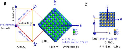
Cesium lead halide perovskite nanocrystals have reached one decade since their simpler synthesis method was reported by Kovalenko and co-workers in 2015. (1) Significant research progress has been made in designing and optimizing the reaction chemistry and optical properties of these emerging light-emitting nanocrystals. (2−9) However, despite the successes achieved for obtaining several such nanocrystals, CsPbBr3 remained in the limelight because of its bright green emission and better phase stability. (3,4,7,10,11) Even in a reaction flask or centrifuge tube, the eye-catching brightness under UV light (12,13) truly excites researchers, and hence, these remained the representative nanocrystals to explore for investigating properties as well as applications of halide perovskite nanocrystals. (2,14−18) Some features of these nanostructures are indeed different, and hence, these occupy some unique positions among all colloidal quantum dots. One such case is their phase–shape relationship. These are largely reported in the orthorhombic phase but mostly in a cube shape. (1−3,19,20) There is also a report on size-dependent phase variation where smaller size is dominated with cubic phase, but these change to orthorhombic for larger sizes. (21) On the other hand, the blue emitting CsPbCl3 nanocrystals are largely reported in the cubic phase with cubic shapes. (1,3) The case of CsPbBr3 having orthorhombic phase and cube shape indeed puzzles as the orthorhombic phase has different atomic parameters but the cube shape has lengths that are equal along all three directions. These cubes are even so monodisperse that their superlattices (22−24) and long-range self-assembly are widely reported. (3,25) Hence, from the standard crystallographic point of view, this confuses from first glance, leading to the belief that these are in the orthorhombic phase. This prompted the writing of this Viewpoint as it was realized that detailed information might help newcomers in the field. In nanoscale synthesis, such exceptions are widely seen in shape modulations where the crystal growth follows paths different than as expected in bulk and facets are dominated by surface ligand binding ability. The CsPbBr3 also remained in such a category of material whose crystal atomic parameters indeed remained unique from their crystal phase to their stability. Keeping this in mind, details of the phase–shape correlation of CsPbBr3 nanocrystals are interpreted with their atomic models and reported in this Viewpoint. These are further supported with high-resolution transmission electron microscopy (HRTEM) image analysis. This Viewpoint is also written from the perspective of synthesis with basic characterization of these materials, which typically confuses new researchers in the field. Figure 1 presents the 3D atomic models of orthorhombic CsPbBr3 (Figure 1a) and cubic CsPbCl3 (Figure 1b) nanostructures in their respective cube shapes. Space groups and atomic parameters for each case are also inserted in each panel. For CsPbBr3, this remained different where three directions parallel to facets of cubes became two ⟨110⟩ and one [001]. These are assigned considering the space group Pbnm with atomic parameters a = 0.8207 nm, b = 0.8255 nm, c = 1.1759 nm. These can also be labeled considering the unit cell parameters a = 0.82 nm, b = 1.17 nm, c = 0.82 nm with space group Pnma, but in that case, the (hkl) values will be changed. For simplicity, here axes remained identical for both halides and the space-filled cubes are placed as per their exact orientations. Accordingly, for CsPbBr3, the projected atomic parameters became 1.164, 1.164, and 1.1759 nm, which remained almost identical. In this case, the [001] direction remained unaltered, but [100] and [010] directions were changed to two ⟨110⟩ directions as shown in Figure 1a. Hence, while viewed along the [001] direction, CsPbBr3 showed 45° rotation to [100] and [010] directions. Accordingly, six facets of the orthorhombic CsPbBr3 cube became (002), (002̅), (110), (1̅1̅0), (11̅0), and (1̅10), whereas for CsPbCl3, these remained as six {100}. In the space filled models, the number of atoms are taken arbitrarily just to represent the shape and are not in exact scale. Figure 1. Atomic models of (a) orthorhombic CsPbBr3 and (b) cubic CsPbCl3 viewed along [001] or c directions. Atomic parameters and space groups for each structure are inserted along with respective models. This suggests that six facets of the cube of CsPbBr3 are not exactly identical even though it retains the shape symmetry of a hexahedron. Hence, the patterns of octahedral arrangements in the atomic models of this perovskite in different viewing directions along their facets are expected to be different. Figure 2a presents the octahedral perovskite atomic model viewed along the [001] direction, and the top and bottom facets here remained (002) and (002̅). These are labeled as {002} because standard planes parallel to these facets are {002} with d-spacing of 0.5879 nm. Accordingly, planes side-to-side are labeled as (110) having d-spacing of 0.582 nm and from corner-to-corner as (200) having d-spacing of 0.41 nm (Figure 2b). On the other hand, the octahedral atomic model viewed along [110] is presented in Figure 2c and the corresponding d-spacing of 0.5879 nm for (002) and 0.413 nm for (11̅2) are presented in Figure 2d, respectively. These labelings are as per the atomic models considered here, but for small crystals it becomes difficult to exactly predict the planes and viewing direction in their HRTEM images. Hence, how to exactly label facets as well as viewing directions becomes important as it could be random or specific considering the view along the [001] or [110] directions. This requires a detailed HRTEM analysis of these nanocrystals. However, before that the crystal phases of these nanocrystals are correlated to distinguish the orthorhombic and cubic phases from the data of powder XRD. Figure 2. Atomic models of CsPbBr3 with (a) octahedra and (b) the standard two-dimensional structure having viewing direction [001]. The same octahedral model (c) and (d) two-dimensional ball model of CsPbBr3 with viewing direction [110]. Cubes synthesized following the method reported by Kovalenko and co-workers (1) typically retain their size below 20 nm. To have larger size nanocrystals for obtaining intense and prominent XRD peaks, multifaceted polyhedral nanocrystals with more than 25 nm size are considered following the method reported using phenacyl bromide as the brominating agent. (26) The XRD of these nanocrystals is presented in Figure 3a where clear differences of (004) and (220) peaks are observed along with prominent small intense peaks confirming these are in the orthorhombic phase. The shape is here similar to the truncated form of a larger cube shape. Figure 3b presents the XRD of films of rhombic dodecahedron-shaped and cube-shaped CsPbBr3 nanocrystals. (26) From the cube shape XRD, (004) and (220) peaks are clearly separated, confirming the orthorhombic phase. Peaks of the cubic phase have similar intense peaks, and for small size cubes, these two peaks are generally seen to be broad and merged. However, several reports with clear explanation already established the fact that these nanocrystals are in the orthorhombic phase. (3,26,27) For comparison, the variation of peak intensities is also observed in the rhombic dodecahedron-shaped nanocrystals which have different facets than the cube shape. In this case, (112) and (200) peak intensities are seen to be more intense than (002)/(110) peaks. XRD of these 12-faceted dodecahedron-shaped nanocrystals is presented here for comparison, and because of their small size, these peaks appear to be merged, resembling the peaks of the smaller size cubic-like phase of CsPbBr3. Variation of XRD peak intensities and sometimes peak splitting are related to several factors, and these might be due to the self-assembly obtained during drop casting, instrumental set up and use of the sample holder, sample preparation, size/shape of particles, and also their dispersity. However, these three examples are presented here as representative ones for comparison. Several such CsPbBr3 nanocrystals are already reported with truncations of edges as well as vertices of cubes to show variation in peak intensities in their XRD. (26,28,29) To relate the facets and shape of these nanocrystals, possible formation of different faceted nanostructures which could originate from truncation of cube shapes or with independent nucleations are presented in Figure 3c. The d-spacing, corresponding (hkl) values, and combinations of planes resulting in a definite shape of nanocrystals are correlated. With exclusive planes having 0.58 nm (0.582 and 0.587 nm), only a cube can be formed as the total number remained 6. Similarly, with exclusive planes with d-spacing 0.41 nm (0.410 and 0.413 nm), 12 faceted nanocrystals would be formed as their total numbers remained 12, including two {200}, two {020}, and eight {112} facets. Furthermore, for the d-spacing of 0.67 nm (0.673 and 0.675 nm), either 4 faceted tetrahedron or 8 faceted octahedrons would be formed. Similarly, combinations of planes can result in 14, 18, and 26 faceted nanocrystals, as shown in the figure. All these shapes’ formations certainly depend on the adopted synthesis procedure; some are already reported, (26,29) and some are yet to be formulated. Figure 3. (a) XRD of ∼40 nm CsPbBr3 polyhedral nanocrystals and inset showing its representative 3D atomic model. (b) XRD of cube and rhombic dodecahedron shaped CsPbBr3 nanocrystals. Arrows marked as (112)/(020) peaks reflect its intensity is more in rhombic dodecahedron shape than cube shape nanocrystals. (c) Different (h, k, l) values and their combinations to reflect different faceted CsPbBr3 nanocrystals. As stated above, the atomic parameters a, b, and c are different for orthorhombic phase, and hence, for a cube, three pairs of facets along three directions cannot be identical. However, as their d-spacings are very close to each other, these show similarity. Hence, confusion arises in labeling planes in HRTEM images whether to label a plane as (110) or (002) as their d-spacing difference cannot be distinguished from the fast Fourier transformed (FFT) patterns. Figure 4 presents one HRTEM image and both possible orientations for plane labeling. Figure 4a shows an HRTEM image of a truncated cube (∼20 nm), and the corresponding selected FFT patten is depicted in both Figure 4b and Figure 4d. Points with similar d-spacings in both FFTs are circled, where yellow is marked for the d-spacing of 0.58 nm and white for 0.41 nm. However, the third digit after the decimal in these cases cannot be identified to designate precisely these planes, and hence, the labeling can bring in different possible orientations. The model in Figure 4c presents a cube viewed along [11̅0], and that in Figure 4e is viewed along [001]; these are labeled as per the FFT labeling in Figure 4b and Figure 4d, respectively. Accordingly, planes having d-spacing of 0.58 nm and 0.41 nm are marked in both cases. Unless the crystal is larger and FFT collected from wider area, it is indeed difficult to identify planes and viewing directions for {110} and {002} or {200} and {112} planes. In most of the reports on cubes, HRTEM images are labeled with planes from side-to-side facets as {110} and corner-to-corner of the cube as {200} assuming the view or zonal axis as [001]. However, this can also be labeled with other possible views. Hence, in practical observation of the HRTEM in small size cubes, either way can be labeled because the HRTEM cannot provide distinguishable differences among {110} and {002} planes. Figure 4. (a) HRTEM of a truncated shape of a CsPbBr3 cube nanocrystal. (b) Corresponding image selected area FFT pattern and (c) representation of model of the cube assuming the viewing direction as [11̅0]. (d) The same FFT as in panel b and the (e) representative model of a cube with viewing direction [001]. (f) Typical shape of cube with viewing direction [001] and a representative FFT pattern, (g) the model of cube along viewing direction [100] and its representative FFT pattern, and (h) representative atomic model of the cube along the viewing direction [201] and corresponding possible FFT pattern. (i) Atomic models showing the nanoplatelet along [001] and [110] directions. Space group for the models of orthorhombic CsPbBr3 is Pbnm (62). The above analysis was for a cube nanocrystal aligned on the TEM grid with one of its facets toward the electron beam. However, the analysis might be different if the nanocrystal is rotated or precipitated with different orientation. Figure 4f presents a 3D atomic model of a cube of CsPbBr3 viewed along [001] direction and the possible FFT pattern on this alignment. In this case, closest planes from center (000) with 90 deg intersects will have d-spacing 0.58 nm. Hence, these can be either of {110} and {002} facets, and in this case, these planes are labeled as (110) and (11̅0) as the viewing direction was assumed as [001]. Similarly, the same cube is shown along the viewing direction [100] where one of the edges of the cube remained along the zone axis and this is presented in Figure 4g. The expected FFT is also presented adjacent to the model, and in this case, two planes perpendicular to each other will have d-spacing of 0.58 and 0.41 nm, respectively. These can be labeled as per the viewing axis, and in this case, these became (200) and (020). The third possibility is the viewing along the vertices, and a representative one is presented in Figure 4h having viewing direction [201]. The corresponding FFT here will show planes having d-spacing of 0.41 nm with intersecting angle of 60°. Planes are assigned here assuming the viewing direction [201]. These three atomic models and their planes are labeled in orthorhombic phase of CsPbBr3, and as per the pattern of the FFT, their planes and viewing directions can be assigned accordingly. If cubic phase is assumed, then the viewing directions would have been ⟨100⟩, ⟨110⟩, and ⟨111⟩, respectively. All the above models are represented for cube shape, which have all six facets similar. However, the question arises for the square platelets as these remained similar to cubes, but growth along one axis is restricted. These are like the cutting piece of a cube structure having the same six facets. These can have two possibilities which might be viewed along [001] or [110] as presented in Figure 4i. A report by Kovalenko and co-workers, (9,30) however, showed distinguished facets of these pseudocubic platelets using X-ray total scattering techniques based on the Debye scattering equation and their HRTEM analysis. They have stated basal planes having square planar surfaces with {110} facets and four rectangular facets with two {110} and two {002} facets as per the space group of orthorhombic phases discussed here. It is expected that four rectangular facets might be four {110} facets and two square facets would be two {002} because of symmetry. However, the results were different, and this might be due to ligand interaction or involvement of some other factors. With the help of probe-corrected HR-scanning transmission electron microscopy imaging it could be possible to identify exact facets, but from the HRTEM images and their FFTs, distinguishing such facets is indeed difficult. On the other hand, cubes which have four {110} and two {002} facets have different octahedral arrangements, as shown in Figure 2, but they maintain symmetry as reflected from their superlattice formation as well as linear attachments. (30) The case of platelets are expected to be different, and more microscopic studies are needed to confirm the same. Typically, for perfect cubes, their alignments on the TEM grid are expected to have one of the six facets along the direction of the electron beam. However, truncated cubes can be orientated in different directions, as projected in Figure 4g,h. These truncations sometimes change the shape of the cubic nanocrystals. During truncation of edges of cubes where these edges are transformed to facets, 12 new facets would appear. As stated above, in cubic phase cubes, these will be 12 {110} facets, whereas for the orthorhombic phase these will be two {200}, two {020}, and eight {112} facets. Similarly, when vertices will be transformed to facets for a cube, in the cubic phase these will be 8 {111} facets, whereas for the orthorhombic phase, these will be 12 {101} facets. In summary, the predictions of facets, planes, and viewing directions of orthorhombic phase CsPbBr3 in cube shape are presented. These are further correlated using different atomic crystal models and HRTEM analysis data. Apart from phase–shape correlations, prediction of directions and planes, their intersecting angles, d-spacing, etc. are also presented, which would help to guide HRTEM analysis and labeling of planes in these nanocrystals. Even during in situ imaging, distances calculated from FFT will immediately help to predict the viewing directions of different shapes, including anisotropic rods or platelets. Hence, it is believed that this Viewpoint will be helpful for analyzing and labeling HRTEM data of different shapes of CsPbBr3 and also for understanding the orthorhombic phase with a cube shape of these emerging halide perovskite nanocrystals. J C Bose Fellowship Research Grant (JCB/2023/000005) is Acknowledged for Funding. This article references 30 other publications. This article has not yet been cited by other publications.
ACS Energy Letters Energy-Renewable Energy, Sustainability and the Environment
CiteScore
31.20
自引率
5.00%
发文量
469
审稿时长
1 months
期刊介绍:
ACS Energy Letters is a monthly journal that publishes papers reporting new scientific advances in energy research. The journal focuses on topics that are of interest to scientists working in the fundamental and applied sciences. Rapid publication is a central criterion for acceptance, and the journal is known for its quick publication times, with an average of 4-6 weeks from submission to web publication in As Soon As Publishable format.
ACS Energy Letters is ranked as the number one journal in the Web of Science Electrochemistry category. It also ranks within the top 10 journals for Physical Chemistry, Energy & Fuels, and Nanoscience & Nanotechnology.
The journal offers several types of articles, including Letters, Energy Express, Perspectives, Reviews, Editorials, Viewpoints and Energy Focus. Additionally, authors have the option to submit videos that summarize or support the information presented in a Perspective or Review article, which can be highlighted on the journal's website. ACS Energy Letters is abstracted and indexed in Chemical Abstracts Service/SciFinder, EBSCO-summon, PubMed, Web of Science, Scopus and Portico.


 分享
分享
 求助内容:
求助内容: 应助结果提醒方式:
 扫码关注我们
